|
Technical:
Runner length
Many customers ask for assistance to determine runner length for their manifold. Many others have a number in mind when they call because they have a baseline from a previous manifold. To help you plan your first attempt or verify your next test, I compiled the following graph. It is compiled from popular formulas, personal experience, and feedback from customers.
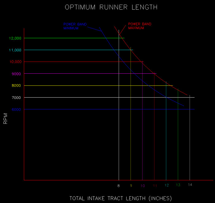
The above graph tends to be more aggressive than conservative. If you have a stick-shift car, it is very close. Automatics tend to need more runner length to accommodate the converter stall and recovery from wider gear changes.
To measure your intake port length, use a length of electrical solder. Straighten the solder and lay it in the port along the floor. Mark it at the valve seat and the manifold gasket face. Straighten it back out and measure between the marks. Repeat for the roof, positioning the solder next to the valve guide. The average of the two measurements is your port length. A ¼” tape measure can also be used instead of solder.
Use the same method to measure the manifold runner length, but don’t wrap the solder or tape measure around the plenum radius. Just extend it tangent to the runner wall, and measure to a straight-edge running across the top of the runners. Most engine builders use the average of the front and back walls of the runner, but some use the floor and roof. It is common to have two or more different runner lengths in a manifold. If so, use an average length for the next calculation.
Add the average runner length, average port length, and manifold gasket thickness, and you have the
total intake tract length.
Example: You have an engine with a 6.25 inch average port length. You want the engine to operate between 8500 and 9500 RPM. From the graph above, you need a total intake tract length of about 10.5”. That leaves 4.25 for the runner length and gasket. With a 0.06” gasket, the average runner length should be 4.19”.
Runner taper
I quantify runner taper by comparing the cross-sectional area of the intake port (at the gasket) versus the area at the plenum opening of the runner (not including the entry fillet). This is expressed as a
percentage of increase in area. I calculate the area at the intake gasket, and then I add the percentage required by the application to determine the runner entry area. Since most applications have round plenum openings, I simply convert the opening area back to the diameter of the required circle.
Obviously, the key is to know what percentage is needed for your application. Several factors seem to be important to determine this number. I can’t quantify the impact of these factors, as every engine combination is different. Camshaft events alone can severely affect how taper is tolerated. I can give you the following relative guidelines to determine where to start:
-
Most drag racing manifolds require between 25% and 45% increase in area. There are applications that go beyond these limits, but this is rare.
-
Engines that are built on production platforms tend to like about 30% increase in area. I’m referring to the typical bore/stroke/rod ratios derived from OEM engines. As bore/stroke ratios approach 1:1, the increase in area is likely to be 25% or less.
-
Race engine platforms with large bores and short strokes like higher percentages – 35-45%.
-
Short deck engines (and resulting rod/stroke ratios) tend to want more taper. The piston motion of a short rod combination will create adequate port velocity in large runners.
-
Stick-shift applications tolerate more taper than automatics.
- Larger displacement engines like more taper than small engines of the same bore/stroke/rod proportions.
These guidelines should help you narrow down your taper requirements within a range of a few percent. The combinations are so varied, even within the same class of racing, that set numbers and fixed rules are difficult to derive. My goal is to minimize your testing iterations required to find the best performance.
Entry Fillets
Changing the fillet radius size at the entry of the runner is another way to tune a manifold. This is particularly relevant in carbureted applications. Fillet size typically varies from ¼” to ½”. If the carburetor signal is weak, a small fillet radius can help the situation because the transition from plenum velocity to runner velocity happens more quickly with a small radius. This extra “snap” can help when attempting to tune large carburetors. This can also be useful when working with larger-than-optimum size plenums. A large radius works well in injected applications and engines with carburetor rules or small plenums.
I like to see larger entry fillets, simply because they are less likely to be turbulent and they have less drag. I do build many manifolds with ¼” fillets with great success, but I pay particularly close attention to the quality of the fillets. The air speed across the fillet can be excessive, and any imperfection is likely to cause turbulence. This is why I prefer machined and polished fillets to the welded and hand-worked fillets typically used on sheet metal manifolds. To demonstrate this, look at the following CFD (computational fluid dynamics) simulation below. As with most complex engineering problems, the simulation is an over-simplified version of real-life conditions. And this, too, is a very simplified version of what happens inside a manifold, but it does confirm one particular instance when filling a cylinder. The plenum was modeled as a large, rectangular open box. The runner is a typical “tilted” runner viewed from the roof. The vacuum condition at the valve end of the runner was increased until an average air speed of 200 to 300 feet per second was achieved, similar to testing on a flow bench. You can see how the air speed along the “short” side of the runner is much higher than anywhere else. You can also see that the velocity peaks at about 500 feet per second as it flows over the entry fillet on the short side (yellow). It requires a nearly perfect shape and surface finish to prevent the air stream from separating from the wall (turbulence) at this speed.
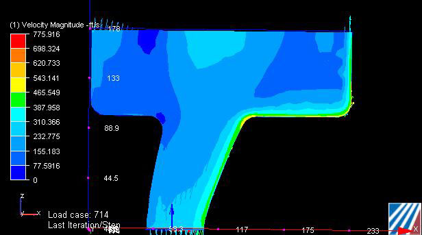
CFD simulation courtesy of Tim Shipp, University of Kentucky
|